News

Which Mechanical Factors Affect the Operating Life of an Isolator Switch?

2026-11-16 0 Leave me a message

An isolator switch does not normally interrupt load current. It opens and closes to provide a visible isolation point for maintenance, and it must remain mechanically sound through thousands of operations over decades of service. The operating life of an isolator switch is therefore not primarily an electrical question. It is a mechanical question. The contacts wear as they slide and close. The operating mechanism accumulates wear at every pivot and latch. The transmission components carry the operating force and absorb any misalignment. The enclosure protects the internal parts from dust and moisture. Each of these factors has a different failure mode and a different specification. A buyer who selects an isolator switch on current rating alone will miss the mechanical factors that determine whether the switch will still operate after ten years in the field.


This guide is written for procurement teams sourcing Isolator Switches for industrial, commercial, and utility applications. It explains the six mechanical factors that most strongly affect operating life: contact design and material, operating mechanism construction, transmission component strength, enclosure and environmental protection, installation and alignment, and operating frequency and load profile. Each section describes the factor, the failure it causes, the specification to check, and the evidence a supplier should provide. The content is organized around the factors rather than a generic product description, so that the procurement discussion focuses on what determines life. It includes the product parameters and documentation that a reliable supplier should provide. Our factory at Wenzhou Xifa Electrical Equipment Co., Ltd. designs Isolator Switches with these factors in mind, and the guidance below reflects the engineering and procurement questions we address with our customers.

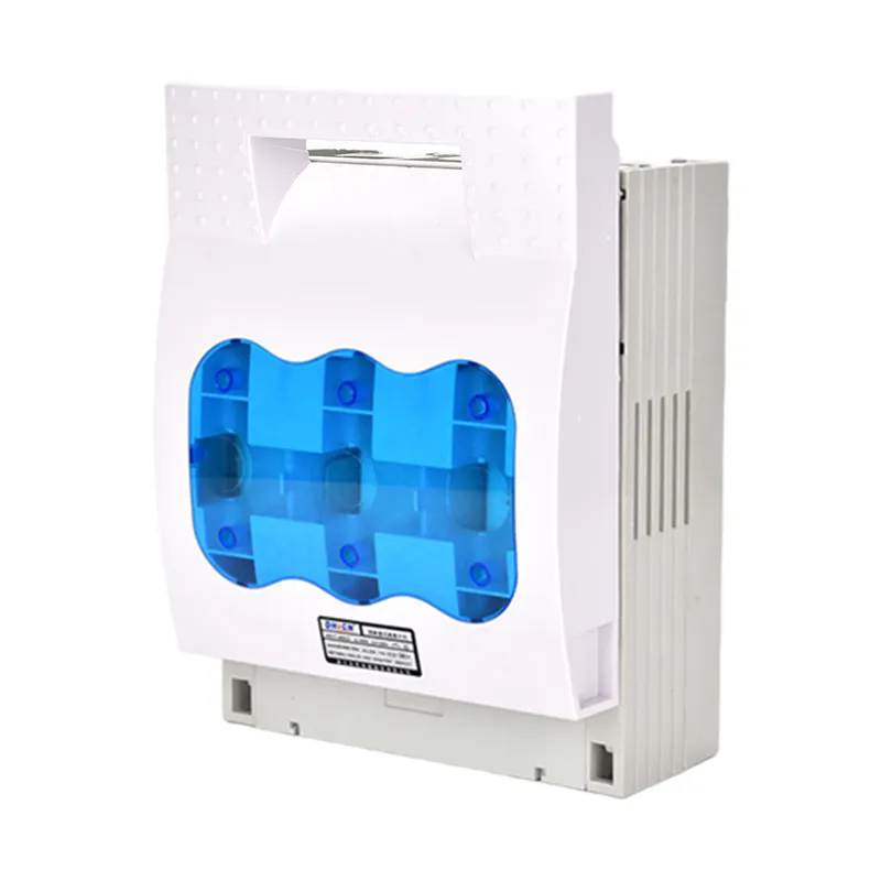
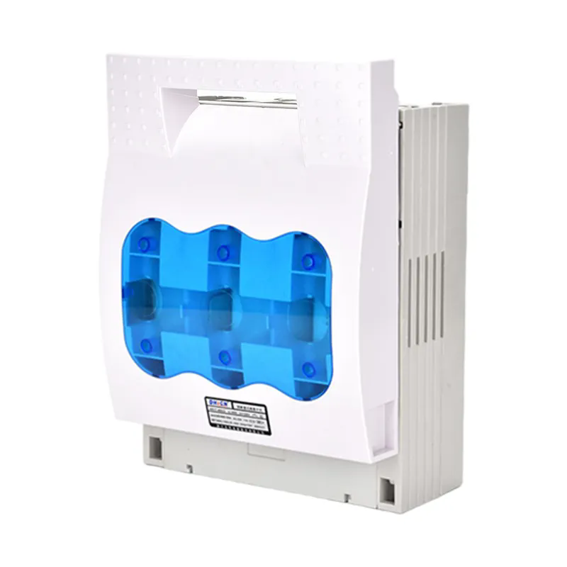
100a fused 3 pole isolator switch


Table of Contents


1. Why Does Contact Design and Material Determine the First Limit of Operating Life?

The contact system is the first limit of operating life because the contacts are the parts that physically separate and rejoin on every operation. In a typical isolator switch, the moving blade or the moving contact slides against the fixed contact, and the sliding action wipes the contact surface. The wiping action is deliberate: it removes oxide and debris and helps maintain a low-resistance contact. But the same wiping action removes a small amount of contact material on every operation. Over thousands of operations, the contact thickness decreases, the contact pressure changes, and the contact resistance rises. The switch may still open and close, but the current-carrying capability is degraded.

The contact material determines how quickly this degradation occurs. Silver-plated copper contacts offer low resistance but the silver layer can wear through. Silver-tungsten or silver-nickel contacts offer better arc erosion resistance but may have higher resistance. The contact geometry determines the contact pressure and the wiping distance. A contact system with a well-designed wiping action and a generous contact thickness will last longer than a system with a minimal contact thickness. The table below summarizes the contact factors and their effect on operating life.

Contact Factor Effect on Operating Life Procurement Check
Contact material Silver-tungsten resists erosion; silver plating wears faster Confirm the material grade and the plating thickness
Contact thickness Thicker contact allows more wiping cycles Request the contact thickness specification
Contact pressure Higher pressure reduces resistance but increases wear Confirm the pressure is within the design range
Wiping distance Longer wipe cleans better but removes more material Confirm the wipe is optimized for the duty
Contact alignment Misalignment causes uneven wear and hot spots Confirm the alignment is controlled in production

Our factory at Wenzhou Xifa Electrical Equipment Co., Ltd. specifies the contact material and the contact thickness for each Isolator Switch model, and we control the contact pressure and the wiping distance in the assembly. We also perform contact resistance measurement on every production batch. The goal is to provide a contact system that maintains its current-carrying capability through the rated number of operations.

For a buyer, the contact specification should be stated in the purchase order, and the supplier should provide the contact material certificate and the contact resistance data. A supplier that provides only the current rating without the contact data is a supplier that is leaving the operating life to chance. The procurement team should also ask whether the contact system is designed for the expected number of operations, because a contact system that is adequate for occasional switching may not be adequate for frequent isolation.


2. How Does the Operating Mechanism Accumulate Wear Over Thousands of Operations?

The operating mechanism accumulates wear at every pivot, latch, and sliding surface. An isolator switch mechanism typically includes a handle or a motor drive, a shaft, a linkage, a latch, and a spring. Each of these components moves relative to its neighbor, and each movement produces friction. Over thousands of operations, the friction removes material from the pins, the bushings, and the latch surfaces. The clearances increase, the operating force changes, and the mechanism may become difficult to operate or may fail to latch in the closed position. The table below describes the wear points and their effect.

Wear Point Wear Mechanism Effect on Operating Life Mitigation
Pivot pins and bushings Sliding friction Increased clearance, lost motion Hardened pins, lubricated bushings
Latch surfaces Contact stress and sliding Failure to latch, partial closure Hardened latch, controlled geometry
Spring Fatigue and relaxation Reduced operating force, slow opening Quality spring steel, stress relief
Shaft bearings Friction and contamination Increased operating torque Sealed bearings, proper lubrication
Manual handle Wear at the coupling Handle slip, difficult operation Hardened coupling, robust design

The mechanism wear is not always visible. A switch that operates smoothly in the first year may become stiff in the fifth year because the lubrication has dried and the pivot pins have worn. The operating force may increase, and the operator may apply more force to compensate, which accelerates the wear. The latch may not engage fully, and the switch may appear closed while the contacts are not fully seated. This is a dangerous condition because the isolation point is not reliable. The mechanism design and the material selection determine how quickly this condition develops.

Our factory at Wenzhou Xifa Electrical Equipment Co., Ltd. designs the operating mechanism of our Isolator Switches with hardened pivot pins, lubricated bushings, and a latch geometry that maintains engagement through the rated life. We perform an operating force test and a latch engagement test on every production batch. The goal is to provide a mechanism that remains easy to operate and reliably latches through the service life.

For a buyer, the mechanism specification should include the operating force, the latch engagement, and the mechanical life rating. The supplier should provide the mechanical life test report, which records the operating force and the latch condition after the rated number of operations. A supplier that provides only a mechanical life number without the test report is a supplier that is making a claim without evidence. The procurement team should request the report and review the test conditions.


3. Why Does Transmission Component Strength Matter for Misalignment Tolerance?

Transmission component strength matters because the isolator switch is often installed with some degree of misalignment between the operating mechanism and the switch shaft. The misalignment may come from the mounting surface, the linkage, or the enclosure. If the transmission components are weak or flexible, the misalignment is absorbed by bending or twisting, which increases the operating force and accelerates wear. If the components are strong and rigid, the misalignment is transferred to the bearings and the shaft, which can also cause wear. The correct design balances strength and compliance so that the transmission can tolerate the expected misalignment without overloading the mechanism.

The transmission components include the shaft, the coupling, the linkage, and the mounting bracket. Each component has a stiffness and a strength. The stiffness determines how the misalignment is distributed. The strength determines whether the component will yield or break under the operating force. The table below summarizes the transmission factors and their effect.

Component Design Factor Effect on Operating Life Procurement Check
Shaft Diameter and material Too flexible: lost motion; too stiff: bearing load Confirm shaft diameter and material grade
Coupling Type and alignment tolerance Rigid coupling transfers misalignment to bearings Confirm the coupling type and tolerance
Linkage Length and pivot design Long linkage amplifies misalignment Confirm the linkage geometry
Mounting bracket Stiffness and flatness Flexible bracket changes operating force Confirm bracket stiffness and flatness

The coupling is often the component that determines the misalignment tolerance. A rigid coupling requires precise alignment, while a flexible coupling can absorb angular and parallel misalignment. The flexible coupling adds cost and complexity, but it protects the bearings and the mechanism. The mounting bracket is the component that determines whether the switch is installed flat. A bracket that is not flat will distort the enclosure and misalign the shaft. The bracket should be designed with a flatness specification and a stiffness that matches the operating force.

Our factory at Xifa supplies Isolator Switches with a range of coupling and mounting options to match the installation conditions. We provide the alignment tolerance for each coupling type and the flatness specification for each bracket. The goal is to provide a transmission design that tolerates the installation conditions without overloading the mechanism.

For a buyer, the transmission specification should be matched to the installation. A switch that is installed on a fabricated frame may need a flexible coupling and a stiff bracket, while a switch installed on a machined panel may use a rigid coupling. The procurement team should provide the installation details to the supplier and confirm the recommended coupling and bracket. A supplier that can advise on the installation is a supplier that understands the operating life implications.


4. How Does the Enclosure and Environmental Protection Affect Internal Wear?

The enclosure and environmental protection affect internal wear because dust, moisture, and corrosive gases accelerate every wear mechanism inside the switch. Dust that enters the enclosure acts as an abrasive between the contacts and the mechanism. Moisture causes corrosion of the contacts and the pivot pins. Corrosive gases attack the silver plating and the copper conductors. The enclosure rating determines how much of these contaminants reach the internal parts. The table below summarizes the environmental factors and their effect on operating life.

Environmental Factor Effect on Internal Parts Enclosure Requirement Procurement Check
Dust Abrasive wear of contacts and mechanism IP5X or IP6X Confirm the IP rating and the test report
Moisture Corrosion of contacts and pivot pins IPX4 or higher, with drain Confirm the sealing and the drain design
Corrosive gases Attack on silver plating and copper Corrosion-resistant coating, sealed enclosure Confirm the material and coating specification
Temperature cycling Condensation inside the enclosure Breather or anti-condensation heater Confirm the condensation control

The enclosure rating is not only about the IP number. The design of the enclosure determines whether the internal parts are protected over time. A sealed enclosure without a breather can develop condensation as the temperature cycles, and the condensation can corrode the contacts. A ventilated enclosure can admit dust, and the dust can abrade the mechanism. The correct design uses a sealed enclosure with a breather membrane or an anti-condensation heater, depending on the environment. The enclosure material also matters: a painted steel enclosure can corrode at the edges and the fixings, while a stainless steel or a molded enclosure is more resistant.

Our factory at Wenzhou Xifa Electrical Equipment Co., Ltd. supplies Isolator Switches with IP65 and IP66 enclosures for dusty and wet environments, and with anti-condensation options for installations that experience temperature cycling. We provide the IP test report and the material certificate with each switch. The goal is to provide an enclosure that protects the internal parts from the environment over the service life.

For a buyer, the enclosure specification should be matched to the installation environment. An outdoor installation needs a higher IP rating and a corrosion-resistant enclosure. An indoor installation in a clean environment may use a lower rating. The procurement team should also confirm the condensation control if the installation experiences temperature cycling. A supplier that can advise on the enclosure selection is a supplier that understands the environmental effect on operating life.


5. What Role Do Installation Alignment and Operating Practice Play?

Installation alignment and operating practice play a role that is often underestimated. An isolator switch that is installed out of alignment will experience higher operating force, uneven contact wear, and accelerated mechanism wear. An isolator switch that is operated with excessive force, or operated while the load is not fully disconnected, will experience contact erosion and mechanism stress that shorten its life. The installation and operating practice are outside the supplier's control, but the supplier can provide the instructions and the design features that make correct installation and operation easier.

The checklist below describes the installation and operating practices that should be followed to achieve the rated operating life.

  • Mount the switch on a flat, rigid surface: The mounting surface should meet the flatness specification and should be rigid enough to prevent distortion of the enclosure.
  • Align the operating mechanism: The linkage or the motor drive should be aligned to the switch shaft within the coupling tolerance. A flexible coupling should be used where the alignment cannot be guaranteed.
  • Verify the operating force: After installation, the operating force should be measured and compared to the specification. An increase in force indicates misalignment or interference.
  • Operate the switch through its full stroke: The switch should be operated from fully closed to fully open and back, and the latch should be confirmed at each position.
  • Do not operate under load unless rated: The isolator switch should not be used to interrupt load current unless it is specifically rated for that duty. Operating under load causes contact erosion and shortens the operating life.
  • Inspect periodically: The switch should be inspected for contact wear, mechanism wear, and enclosure condition at the recommended interval.

Our factory at Wenzhou Xifa Electrical Equipment Co., Ltd. provides installation instructions and operating guidance with every Isolator Switch. We also provide the operating force specification and the alignment tolerance for the coupling. The goal is to give the installation team the information needed to achieve the rated operating life.

For a buyer, the installation and operating practice should be included in the procurement package. The supplier should provide the installation manual and the maintenance schedule, and the buyer should confirm that the installation team has the information. A supplier that provides only the product without the installation guidance is a supplier that is leaving the operating life to the installer's judgment.


6. What Should Procurement Verify Before Ordering?

Procurement should verify the mechanical factors as a system, not as a single specification. The verification should cover the contact system, the mechanism, the transmission, the enclosure, and the documentation. The checklist below provides the verification steps for an Isolator Switch.

Verification Step What to Request Acceptance Criterion
Contact specification Material, thickness, pressure, wiping distance Matched to the operating frequency
Mechanism life report Operating force and latch condition after rated operations Within the specified limits
Transmission specification Shaft, coupling, linkage, bracket data Matched to the installation conditions
Enclosure IP report Third-party IP test report Meets the environment requirement
Installation manual Mounting, alignment, operating instructions Complete and clear
Maintenance schedule Inspection interval and wear limits Matches the expected service life

Our factory at Wenzhou Xifa Electrical Equipment Co., Ltd. provides the contact data, the mechanism life report, the transmission specification, the IP report, and the installation manual for our Isolator Switches. We also welcome customer audits and can provide samples for evaluation. The goal is to make the verification process transparent and to give buyers the evidence they need to confirm that the switch will achieve its rated operating life.

For a buyer, the verification should include a review of the supplier's production control. A contact system that is correct in the design may be compromised in production if the contact pressure is not controlled, the alignment is not checked, or the enclosure is not sealed correctly. The procurement team should confirm that the production process includes the contact resistance test, the operating force test, and the IP test at the specified sampling frequency.


7. Frequently Asked Questions (FAQ)

Question 1: What is the most common mechanical cause of isolator switch failure?

Answer: The most common mechanical cause is wear at the contact system and the operating mechanism. The contacts wear as they wipe on every operation, and the mechanism wears at the pivot pins and the latch. The wear increases the operating force and the contact resistance, and it can eventually cause the switch to fail to latch or to carry current reliably. Regular inspection and correct installation help slow the wear, but the contact and mechanism design determine the ultimate life.

Question 2: How does the operating mechanism design affect the mechanical life of an isolator switch?

Answer: The mechanism design determines how the operating force is transmitted and how the wear is distributed. A mechanism with hardened pivot pins, lubricated bushings, and a well-designed latch maintains a low operating force and reliable latching through thousands of operations. A mechanism with soft pins, dry bushings, or a poor latch geometry wears faster and may become difficult to operate. The mechanical life test report shows the operating force and the latch condition after the rated operations.

Question 3: Why does installation alignment matter for an isolator switch?

Answer: Installation alignment matters because misalignment between the operating mechanism and the switch shaft increases the operating force and causes uneven contact wear. The increased force accelerates the mechanism wear, and the uneven wear reduces the contact life. A flexible coupling and a flat, rigid mounting surface help maintain alignment. The installation manual should specify the alignment tolerance and the mounting flatness.

Question 4: Can an isolator switch be operated under load?

Answer: An isolator switch should not be operated under load unless it is specifically rated for that duty. The isolator is designed to provide a visible isolation point, not to interrupt load current. Operating under load causes contact erosion and shortens the operating life. If load breaking is required, a switch-disconnector with the appropriate load-breaking rating should be selected.

Question 5: What documentation should accompany an isolator switch order to verify mechanical life?

Answer: The order should include the contact specification, the mechanism life test report, the transmission specification, the enclosure IP test report, the installation manual, and the maintenance schedule. These documents allow the buyer to verify that the switch is designed for the expected operating life and that the installation and maintenance requirements are understood. A supplier that provides this documentation is a supplier that is managing the mechanical life of the product.


8. Conclusion

The operating life of an Isolator Switch is determined by mechanical factors: the contact design and material, the operating mechanism construction, the transmission component strength, the enclosure and environmental protection, and the installation and operating practice. Each factor has a different failure mode, and each factor requires a different specification. For procurement teams, the verification should cover the contact data, the mechanism life report, the transmission specification, the IP report, and the installation manual. Our factory at Wenzhou Xifa Electrical Equipment Co., Ltd. designs Isolator Switches with these factors in mind and provides the documentation that buyers need to confirm the mechanical life. If you are sourcing isolator switches and need to verify the mechanical factors, contact our team to discuss your operating requirements and to request the contact, mechanism, and enclosure data for your application.


Contact Wenzhou Xifa Electrical Equipment Co., Ltd. today to discuss your Isolator Switch requirements and to request the mechanical life documentation for your application.

Related News
Leave me a message
X
We use cookies to offer you a better browsing experience, analyze site traffic and personalize content. By using this site, you agree to our use of cookies. Privacy Policy
RejectAccept