News

What Makes Current Transformers the Key Sensor for Electrical Metering Systems?

2026-09-04 0 Leave me a message

In a bustling data center filled with thousands of servers, every watt of power consumed must be monitored with precision. The facility manager relies on a network of meters to track energy usage, identify inefficiencies, and allocate costs. At the heart of each of these meters lies a Current Transformer CT—an unassuming sensor that silently performs one of the most critical tasks in electrical measurement. Without this component, accurate power monitoring would be nearly impossible. Current transformers are the essential bridge between the high-voltage, high-current world of power distribution and the sensitive, low-power electronics of modern metering systems.


So what makes a Current Transformer CT the key sensor for electrical metering systems? The answer lies in three fundamental capabilities: precise current measurement across a wide dynamic range, complete galvanic isolation between the primary circuit and the measurement equipment, and the ability to provide a standardized, low-current output that is easily processed by meters and protection relays. This article will explore the design principles, performance characteristics, and application considerations that make current transformers indispensable in electrical metering. From the physics of magnetic induction to the practical challenges of accuracy and saturation, we will dissect the engineering that enables these devices to deliver reliable measurements in everything from residential submeters to high-voltage substations.

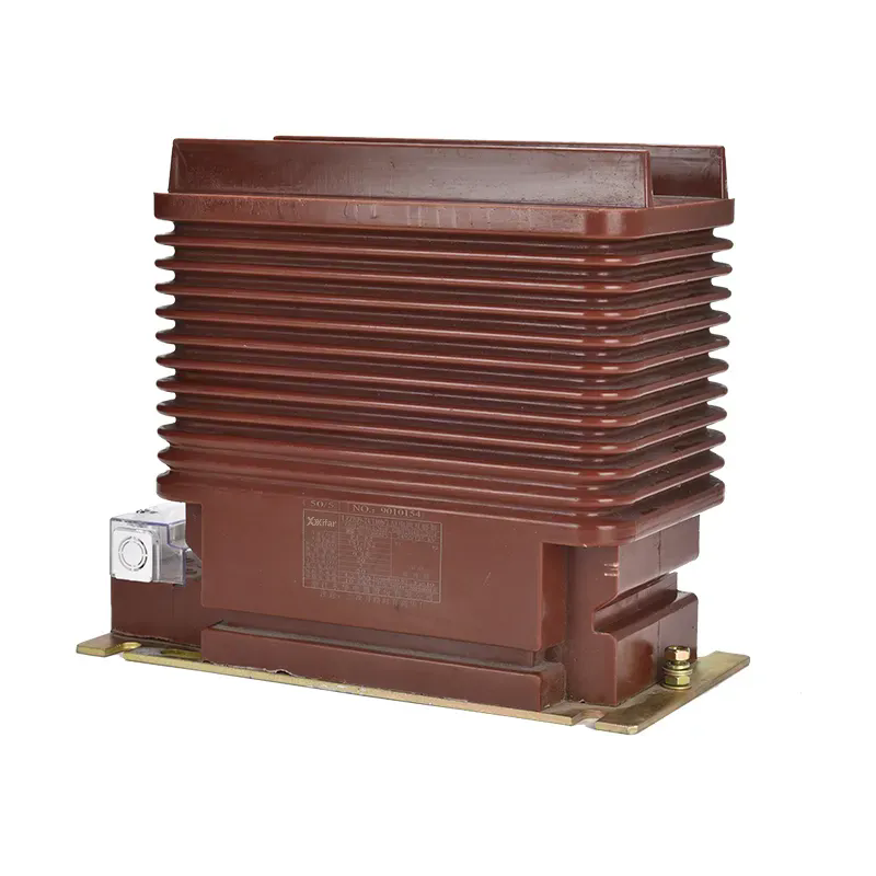
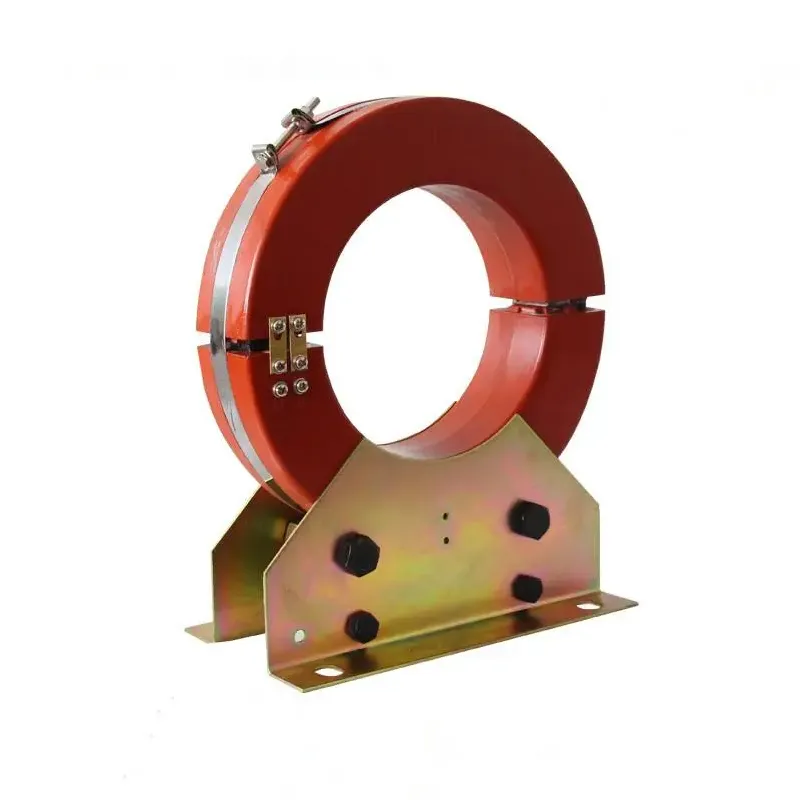
current transformer ct 200 300 500 800 5a


Table of Contents


1. What Is a Current Transformer CT and How Does It Work?

A Current Transformer CT is a type of instrument transformer designed to produce a reduced, accurately scaled current that is proportional to the current flowing in a primary conductor. It is a passive device that operates on the principle of electromagnetic induction. The primary conductor—the wire carrying the current to be measured—passes through the CT's core, which is typically a ring of high-permeability magnetic material such as silicon steel or a nanocrystalline alloy. This primary conductor acts as a single-turn primary winding. The secondary winding, consisting of many turns of insulated copper wire wound around the core, provides the output current. When alternating current flows through the primary conductor, it creates a varying magnetic flux in the core. This flux induces a current in the secondary winding that is proportional to the primary current, scaled by the turns ratio.

Imagine a current transformer as a precision scale that measures the weight of an elephant by weighing a small, representative sample. The primary current is the elephant—large and unwieldy. The secondary current is the small sample—easy to measure and safe to handle. The CT's turns ratio determines the scaling factor. For example, a 1000:5 CT means that when 1000 amperes flow through the primary, 5 amperes will flow through the secondary circuit. This standardized 5 A (or 1 A) secondary output allows meters, relays, and other monitoring equipment to be manufactured as standardized, interchangeable devices, without needing to be designed for the high currents and voltages of the primary circuit. This is the fundamental reason why the Current Transformer CT is the backbone of modern electrical metering.

The core material is a critical factor in the CT's performance. The core must have high permeability to efficiently concentrate the magnetic flux, and it must have low hysteresis to minimize losses. The core must also have a linear magnetization curve to ensure that the ratio between primary and secondary currents remains constant across the entire range of currents. At Wenzhou Xifa Electrical Equipment Co., Ltd., we manufacture Current Transformer CT cores using high-quality grain-oriented silicon steel, selected for its excellent magnetic properties and low coercivity. Our factory's experience in core design and winding technology ensures that our current transformers deliver reliable, accurate performance across a wide range of applications.


2. What Makes Current Transformers Essential for Safe Metering?

Safety is the primary reason why current transformers are used in metering applications. Directly connecting a meter to a high-current, high-voltage circuit would be extraordinarily dangerous. The meter would need to be rated for the full primary voltage (which could be hundreds of kilovolts) and current (which could be thousands of amperes). This would be physically large, prohibitively expensive, and inherently hazardous. The Current Transformer CT elegantly solves this problem by providing galvanic isolation. There is no direct electrical connection between the primary circuit and the secondary circuit. The primary is separated from the secondary by the insulation of the core and the physical distance between the windings. This isolation ensures that the meter and the operator are not exposed to the dangerous voltages and currents of the primary system.

The secondary circuit of a Current Transformer CT is designed to be safe to work with. The typical secondary output is either 5 A or 1 A, which is readily handled by standard meters and protection relays. The voltage across the secondary terminals is also kept low. This safety aspect is not just a convenience; it is a fundamental safety requirement. The secondary circuit of a CT must never be opened while the primary is energized. If the secondary circuit is open, the high impedance of the secondary terminals will cause the core flux to rise to dangerous levels, generating a high voltage that can be lethal to personnel and destructive to equipment.

For metering applications, this safety is paramount. A Current Transformer CT allows a meter to be installed safely in a location that is convenient for reading and maintenance. The meter can be placed in a panel, mounted on a wall, or even located remotely from the primary circuit. This is especially important in modern data centers, industrial facilities, and commercial buildings where centralized energy management systems require accurate measurement at multiple points. Our factory at Xifa designs its Current Transformer CT with safety in mind, using high-quality insulation materials and robust construction to ensure reliable isolation over the life of the product.


3. How Do Accuracy Classes Define CT Performance?

For any metering application, accuracy is the most critical performance parameter. The accuracy of a Current Transformer CT is expressed in terms of its accuracy class, which defines the allowable error in the ratio between the primary and secondary currents and the allowable phase displacement. The accuracy class is specified by a combination of a letter and a number. For metering applications, the most common accuracy classes are 0.1, 0.2, 0.5, 1, and 3. The number indicates the maximum percentage error at rated current. For example, a Class 0.5 CT has a maximum ratio error of 0.5% at the rated current.

The phase displacement is also critical for accurate power measurement. In a three-phase system, phase errors in the CTs can cause significant errors in the measurement of active and reactive power. The accuracy class also defines the maximum phase displacement. For example, a Class 0.5 CT has a maximum phase displacement of 20 minutes (0.33 degrees). The accuracy class is measured at a specific burden (load) and at a specific percentage of rated current (typically 100%). The accuracy of a CT is not constant over its entire range; it is typically most accurate at the rated current and degrades at very low currents and at currents above the rated value.

The following table summarizes the accuracy classes and their typical metering applications.

Accuracy Class Max Ratio Error Max Phase Displacement Typical Application
0.1 0.1% 5 minutes Precision metering, calibration, standards
0.2 0.2% 10 minutes High-accuracy revenue metering
0.5 0.5% 20 minutes Commercial and industrial metering
1.0 1.0% 60 minutes General-purpose metering
3.0 3.0% Not specified Indication only

Choosing the correct accuracy class is a critical decision. For revenue metering applications, where the measurements are used for billing, a higher accuracy (0.1 or 0.2) is essential. For submetering and general monitoring, a Class 0.5 or 1.0 CT is typically sufficient. The required accuracy class also depends on the burden of the meter. The meter must have a low enough burden to ensure the CT operates within its specified accuracy limits. At Wenzhou Xifa Electrical Equipment Co., Ltd., we offer a full range of Current Transformer CT accuracy classes to suit the needs of our customers, from high-accuracy revenue metering to general monitoring applications.


4. What Design Features Enable Wide Dynamic Range?

One of the key advantages of a Current Transformer CT is its ability to measure currents accurately across a wide range, from small fractional currents to large overload currents. This dynamic range is essential for modern electrical metering systems, which must accurately measure energy consumption during periods of both light and heavy load. The dynamic range of a CT is primarily determined by the core material and the winding design. The core must be able to operate linearly over a wide range of flux densities. The winding must be designed to minimize leakage inductance and to provide a stable turns ratio.

The core material is the most critical factor in achieving a wide dynamic range. The core must have a linear magnetization curve, meaning that the flux density is proportional to the magnetizing force, up to the saturation point. A high-permeability core, such as grain-oriented silicon steel, has a relatively linear region over a wide range of currents. The core must also have a low coercivity to minimize hysteresis and ensure that the CT maintains its accuracy over time. The core material is also selected to have a high saturation flux density to prevent the core from saturating under fault conditions. The core geometry is also important; a core with a large cross-sectional area can handle a larger flux without saturating.

The winding design also affects the dynamic range. The secondary winding is typically wound with a large number of turns to produce a high output voltage per ampere of primary current. This high sensitivity allows the CT to measure small currents accurately. The winding is designed to minimize leakage inductance, which can cause errors at high frequencies and during transient conditions. The insulation between the turns must be robust to prevent short circuits. The winding must also be designed to handle the rated current without overheating. Our factory at Wenzhou Xifa Electrical Equipment Co., Ltd. uses advanced winding techniques and high-quality materials to ensure that our Current Transformer CT provide a wide dynamic range and consistent performance across their entire operating range.

The core and winding design must also account for the effect of burden. The burden is the impedance of the secondary circuit, including the meter, the leads, and the connecting terminals. A high burden can reduce the effective dynamic range of the CT and can cause saturation at relatively low currents. It is important to select a CT with a rating that is appropriate for the expected burden. A CT with a high burden rating will have a larger core and more turns, resulting in a wider dynamic range. Our technical team can assist in calculating the appropriate burden for your application.


5. How Do Burden and Saturation Affect Measurement Accuracy?

Two critical factors that affect the accuracy and performance of a Current Transformer CT are burden and saturation. Burden is the total impedance of the secondary circuit, including the meter, the connecting leads, and the termination points. If the burden is too high, the CT's output voltage will be forced to rise, causing the core flux to increase, which can lead to saturation. Saturation occurs when the core flux density reaches the material's maximum flux density, beyond which an increase in primary current does not result in a proportional increase in secondary current. This causes the CT to produce a distorted output signal, leading to inaccurate measurements.

The relationship between burden and saturation is a critical design consideration. A CT is rated for a specific burden, typically expressed in VA (volt-amperes). For example, a CT with a rating of 5 VA can drive a secondary circuit with a total impedance of up to 0.2 ohms at 5 A (since P = I²R). If the burden exceeds this rating, the CT may saturate at a lower primary current, limiting its dynamic range and causing measurement errors. It is essential to select a CT with a burden rating that is higher than the actual burden of the meter and the connecting leads.

To ensure accurate measurement, the CT should be operated well below its saturation point. The margin between the operating flux and the saturation flux is called the "saturation margin." A CT with a high saturation margin will be more resistant to saturation and will maintain its accuracy over a wider range of currents. The saturation margin is determined by the core material, the core geometry, and the number of turns. CTs designed for metering applications typically have a high saturation margin to ensure they can handle overloads without loss of accuracy. The following table illustrates the effect of burden on the measurement accuracy of a typical Current Transformer CT.

Burden (% of Rated) Measurement Error (%) Effect
25% 0.1% Within specification, accurate measurement
50% 0.15% Within specification, accurate measurement
100% 0.3% At rated burden, slight increase in error
150% 1.5% Excessive burden, significant error
200% 5.0% Severe saturation, unreliable measurement

The burden should always be carefully calculated and verified during the design phase of a metering system. A CT with a higher VA rating can handle a higher burden, but it is also larger and more expensive. A CT with a lower VA rating is smaller and less expensive, but it is more sensitive to burden and may saturate under heavy loads. At Xifa, we offer a range of Current Transformer CT with different burden ratings to suit the specific requirements of different metering applications. Our technical team can assist in selecting the right CT for your application.


6. How to Select the Right Current Transformer CT for Your Application?

Selecting the right Current Transformer CT for a metering application involves a systematic evaluation of the system's current, voltage, and accuracy requirements. The following selection framework provides a step-by-step approach to ensure that the CT is correctly specified. The first step is to determine the primary current range. The CT must be able to measure the maximum operating current accurately, and it must also be able to withstand the maximum fault current without damage. The CT's rated current should be chosen to be approximately 60-80% of the maximum anticipated load current, providing some margin for future load growth. The CT's dynamic range should also be considered, ensuring that it can accurately measure the minimum and maximum currents.

The second step is to determine the required accuracy class. For revenue metering, a high accuracy class (0.1 or 0.2) is required. For submetering and general monitoring, a lower accuracy class (0.5 or 1.0) may be sufficient. The accuracy class must also be matched to the burden of the meter. The third step is to determine the burden. The burden must be calculated based on the meter's input impedance, the length of the connecting leads, and the impedance of any intermediate devices. The CT must have a burden rating that is greater than the calculated burden.

The following table summarizes the key selection criteria and provides typical values for a Current Transformer CT.

Selection Criterion Considerations Typical Values
Primary Current (A) Maximum continuous load current 50, 100, 200, 400, 800, 1000, 2000
Secondary Current (A) Standard output for meters 5 A or 1 A
Accuracy Class Required measurement precision 0.1, 0.2, 0.5, 1.0
Burden (VA) Total impedance of secondary circuit 2.5, 5, 10, 15, 30
Insulation Level Rated voltage of primary circuit 0.6 kV, 12 kV, 24 kV, 36 kV
Frequency (Hz) Mains frequency 50 Hz or 60 Hz

Additional factors to consider include the insulation level, the frequency, and the ambient temperature. The CT must be designed for the voltage level of the primary circuit. For high-voltage applications, the CT must have adequate insulation and creepage distances. The CT must be designed for the mains frequency (50 Hz or 60 Hz). The ambient temperature affects the CT's performance and its ability to dissipate heat. At Xifa, we manufacture Current Transformer CT for a wide range of applications, from low-voltage distribution to high-voltage substation metering. Our products are designed to meet the relevant international standards and are rigorously tested to ensure reliable performance.


7. Frequently Asked Questions (FAQ)

Question 1: What is the difference between a current transformer and a voltage transformer?

Answer: A current transformer (CT) is used to measure current and is connected in series with the circuit. A voltage transformer (VT) is used to measure voltage and is connected in parallel. The CT produces a secondary current proportional to the primary current, while the VT produces a secondary voltage proportional to the primary voltage. They are both instrument transformers used for metering and protection. The Current Transformer CT is the key sensor for measuring current in power systems.

Question 2: Can I install a current transformer CT in any orientation?

Answer: While a Current Transformer CT can be installed in most orientations, it is generally recommended to follow the manufacturer's guidelines. The orientation does not significantly affect the accuracy at normal operating currents. However, for high-accuracy applications, it is advisable to ensure that the core is not subjected to excessive vibration or magnetic fields. For split-core CTs, care should be taken to ensure that the core is properly closed and secured to maintain accuracy.

Question 3: How do I choose between a 5 A and a 1 A secondary CT?

Answer: The choice between a 5 A and a 1 A secondary Current Transformer CT depends on the metering equipment and the distance between the CT and the meter. A 5 A output is more common and provides a higher signal level, which can be advantageous in noisy environments. A 1 A output is often used for long-distance transmission because the lower current reduces voltage drop in the leads. Most modern meters support both 5 A and 1 A inputs. Our factory can provide guidance on the optimal choice for your specific application.

Question 4: What causes a current transformer CT to saturate?

Answer: A Current Transformer CT saturates when the magnetic flux in the core reaches its maximum limit. This typically occurs when the primary current exceeds the CT's rated capacity by a large margin, or when the secondary burden is too high. Saturation can also be caused by a high DC component in the primary current or by excessive system frequency. When a CT saturates, its output current becomes distorted and non-proportional to the primary current, leading to inaccurate measurements and potential protection maloperation. Our factory tests each CT for saturation characteristics to ensure reliable performance under fault conditions.

Question 5: What are the advantages of using a split-core CT for metering?

Answer: A split-core Current Transformer CT offers several advantages, particularly for retrofit installations. The core can be opened and clamped around the primary conductor without disconnecting the conductor. This makes installation much easier and faster, especially in existing systems where disconnection is difficult or costly. Split-core CTs are also useful for temporary monitoring applications. However, split-core CTs typically have lower accuracy than solid-core CTs of the same class. For high-accuracy applications, a solid-core CT is preferred. Our split-core Current Transformer CT products are designed to provide good accuracy while offering the convenience of easy installation.


8. Conclusion

Current transformers are the unsung heroes of electrical metering systems. They provide the critical function of accurately measuring high currents while ensuring the safety of personnel and equipment. Their ability to provide galvanic isolation, produce a standardized low-current output, and operate reliably over a wide dynamic range makes them indispensable for modern energy monitoring, billing, and protection applications. From the physics of magnetic induction to the practical considerations of burden and saturation, the Current Transformer CT is a testament to the power of simple, robust engineering.

Selecting the right Current Transformer CT for your application requires careful consideration of accuracy, burden, and system requirements. By understanding these factors, you can ensure that your metering system provides the reliable, accurate data needed for effective energy management. At Wenzhou Xifa Electrical Equipment Co., Ltd., we are committed to providing high-quality Current Transformer CT that meet the most demanding metering requirements. Our products are designed and manufactured to the highest standards, ensuring reliable performance over the life of the installation.

Related News
Leave me a message
X
We use cookies to offer you a better browsing experience, analyze site traffic and personalize content. By using this site, you agree to our use of cookies. Privacy Policy
RejectAccept